Iranian Classification Society Rules

< Previous | Contents | Next >
Section 5 Design and Analysis of Other Major Hull Structural Features
501. General
The design and analysis criteria to be applied to the other pertinent features of the hull structural de- sign are to conform to this Guidance or Rules for the Classification of Steel Ships. For ship-type unit, the hull design will need to consider the interface between the position mooring system and the hull structure or the effects of structural support reactions from deck-mounted (or above-deck) equipment modules, or both. The interface structure is defined as the attachment zone of load transmission be- tween the main hull structure and hull mounted equipment, such as topside module stools, crane pedes-
tals etc.
and foundations, riser porches, flare boom foundation, gantry foundation, mooring and offloading, The zone includes components of the hull underdeck structures in way of module support stools
and foundations, such as deck transverse web frames, deck longitudinals and upper parts of longitudinal
and transverse bulkhead structures, as well as foundations of the hull-mounted equipment. These com- ponents of the interface structure should comply with the criteria indicated in 504.. The criteria to be applied for the interface structures are presented below. When it is permitted to base the design for FPSO on site-specific environmental conditions, reference is to be made to 301., 401. and 503. of this Guide regarding how load components can be adjusted.
502. Hull interface structure
The basic scantlings in way of the hull interface structure is to be designed based on the first princi- ple approach and meet the requirements of strength criteria in Rules for the Classification of Mobile Offshore Drilling Units or equivalent national industry standards recognized and accepted, such as API Standards. Welding design of hull interface structure connections is to be developed based on Pt 12, Ch 6, Sec 5 of Rules for the Classification of Steel Ships or a direct calculation approach. Material grades for the above deck interface structure are to be selected as per Rules for the Classification of Mobile Offshore Drilling Units. The material grades for the hull structure components, such as deck and frame structures, are to be selected as per Pt 3 of Rules for the Classification of Steel Ships. The verification of the hull interface structure as defined above is to be performed using direct calculation of local 3-D hull interface finite element models, developed using gross scantlings and analyzed with load conditions and load cases described in the following sections.
1. Position mooring/hull interface modeling
A FEM analysis is to be performed and submitted for review.
(1) Turret or SPM Type Mooring System, External to the Installation’s Hull
If the mooring system is of the turret or SPM type, external to the installation’s hull, the fol- lowing applies:
(A) Fore end mooring - The minimum extent of the model is from the fore end of the in- stallation, including the turret structure and its attachment to the hull, to a transverse plane
after the aft end of the foremost cargo oil
tank in the installation. The model can be con-
sidered fixed at the aft end of the model. The loads modeled are to correspond to the worst-case tank loads, seakeeping loads as determined for both the transit condition and the
![]()
on-site design environmental condition (DEC), ancillary structure loads, and mooring and ris- er loads for the on-site DEC, where applicable. The design operating condition (DOC) may also need to be considered for conditions which may govern.
(B) Aft end mooring - The minimum extent of the model is from the aft end of the installation and including the turret structure and its attachment to the hull structure to a transverse plane forward of the fore end of the aft most cargo oil tank in the hull. The model can be
considered fixed at the fore end of the model. The loads modeled are to correspond to the
worst-case tank loads, seakeeping loads as determined for both the transit condition and the on- site design environmental condition (DEC), ancillary structure loads, and mooring and ris- er
loads for the on-site DEC, where applicable.
(2) Mooring system internal to the Installation Hull (Turret Moored)
(A) Aft end mooring - The minimum extent of the model is from the aft end of the installation and including the turret structure, its attachment to the hull structure to a transverse plane
forward of the fore end of the aft most cargo oil tank in the hull. The model can be con-
sidered fixed at the fore end of the model. The loads modeled are to correspond to the worst-case tank loads, seakeeping loads as determined for both the transit condition and the on-
site design environmental condition (DEC), ancillary structure loads, and mooring and ris- er loads for the on-site DEC, where applicable.
(B) Midship turret - The model can be a 3-tank model similar to that described in Pt 12, Appendix B of Rules for the Classification of Steel Ships where the turret is located in the center tank of the model. Hull girder loads are to be applied to the ends of the model. The loads modeled are to correspond to the worst-case tank loads, seakeeping loads as determined for either the transit condition or the on-site design environmental condition (DEC), ancillary structure loads, and mooring and riser loads for the on-site DEC, where applicable. The design operating condition (DOC) may also need to be considered for con- ditions which may govern.
(C) As a minimum, the following two cargo loading patterns that result in the worst load ef- fects on the hull structure are to be considered.
(a) Maximum internal pressure for fully filled tanks adjacent to the hold containing the tur- ret, with the other tanks empty and minimum external pressure, where applicable. (See
Fig 5.6)
(b) Empty tanks adjacent to the hold containing the turret, with the other tanks full and maximum external pressure, where applicable. (See Fig 5.7)
The interface structure is to be assessed for yielding, buckling and fatigue strength, and should include all structural members and critical connections within the hold containing the
turret as well as the hold boundaries and their attachments.
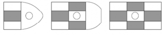
Fig 5.6 Loading Pattern with 2/3 Scanting Draft

Fig 5.7 Loading Pattern with Scanting Draft
(3) Spread Moored Installations
The local foundation structure and installation structure are to be checked for the given mooring loads and hull structure loads, where applicable, using an appropriate FEM analysis. The moor- ing loads to be used in the analysis are to be based on the on-site design environmental con- dition (DEC) for hull structure, and the mooring loads for the on-site DEC and breaking
![]()
strength of the mooring lines. The design operating condition (DOC) may also need to be con- sidered for conditions which may govern.
2. Hull mounted equipment interface modeling
(1) Topside Module Support Stools and Hull Underdeck Structures
The topside module support stools and hull underdeck structures in way of module support stools, such as deck transverse webs, deck longitudinals, longitudinal and transverse bulkheads, are to be assessed for the most unfavorable load combinations of topside stool reactions and hull structure loads, where applicable, using an appropriate FEM analysis. The load combinations of topside stool reactions and hull structure loads are to be consistent with those assumed in the module analysis. The finite element model extent is to be sufficiently large to minimize the cut boundary effects. The openings in way of critical areas are to be incorporated into the FEM model to investigate their effects. The loads for the on-site design operating condition (DOC), on-site design environmental condition (DEC) and transit condition are to be taken into account. Topside production and support systems are to be empty in transit condition. Special attention is to be given to the cutouts in deck transverse webs in way of topside module stools. The strength analysis for the typical cutout with the maximum topside stool reactions using a local fine mesh FEM model is to be carried out and submitted for review.
(2) Other Hull Mounted Equipment Foundation Structures
Other hull mounted equipment foundations, such as crane pedestals and foundations, riser porch- es, flare boom foundations, gantry foundations, offloading equipment foundations, etc., and hull vessel structure in way of the foundations are to be checked for the given functional loads, en- vironmental loads and hull structure loads, where applicable, using an appropriate FEM analysis. The finite element model extent is to be sufficiently large to minimize the cut boundary effects. Openings such as cutouts in way of critical areas are to be incorporated into the FEM model. The loads for the on-site design operating condition (DOC), on-site design environmental con- dition (DEC) and transit condition are to be taken into account in the analysis. All equipment is to be in the stowed position for the transit condition.
503. Loads
1. Load conditions
For all conditions, the primary hull girder load effects are to be considered, where applicable.
(1) Site Design Environmental Condition (DEC)
(A) For non-disconnectable structures
Site DEC with hull design return period, and severe storm functional dead and live loads,
as applicable, with 1/3 stress increase allowable (i.e., 0.8*XŻ )
(B) For disconnectable structures
Site Disconnectable Environmental Condition (DISEC), Client-specified site year return loads
and severe storm functional, dead and live loads (i.e., excluding tropical cyclones), as appli-
cable, with 1/3 stress increase allowable (i.e., 0.8*XŻ )
(C) For the DEC and DISEC load conditions, the following assumptions are applicable
(a) Topside Production Facility modules are in wet condition for all site conditions and in
dry conditions for unrestricted service and transit conditions.
(b) Cranes are in stowed position
(c)
Mooring loads in the most severe hull loading condition are determined from the site mooring load analysis for the following conditions
- All lines are intact
- One line is damaged
For each individual line and associated fairlead, chock, chain stopper etc., the strength is to be assessed under the breaking strength of the line/chain with a Utilization Factor, UF =
0.8 for component stress, 0.9 for Von Mises element stress and 0.8 for buckling stress, in the case that the mooring loads in the above two conditions are not available.
(2) Site Design Operating Condition (DOC)
Site DOC with maximum functional live loads under site operation without 1/3 stress increase
allowable (i.e., 0.6*XŻ ). Special consideration should be given to the following.
(A) Limiting environmental condition, specified by designer/operator, that would require suspen-
sion of normal operations, is to be minimum 1-year return as per this Guide.
(B) Deck support stools for topside production facility modules are in wet condition.
![]()
(C) Crane functional loads are as per API RP 2A and API Spec 2C Practices.
(D) Position mooring hull interface
(3) Transit Condition
For transit (topside production facility in dry condition), it is the shipyard’s and/or designer‘s re-
sponsibility to specify the design parameters for the transit approaches available.
(A) Specified maximum seasonal weather routing condition.
(B) Maximum 10-year return response based on the worst ciated wave scatter diagram along the transit route.
(C) Maximum 10-year return response based on a composite
condition. There are generally four
environmental conditions and asso- wave scatter diagram
(D) North Atlantic service condition, with a minimum 10-year return period, using the IACS
standard wave data where the transit route is not yet defined or finalized.
(4) Damage Condition
Damaged Conditions (as applicable) with static deadweight and functional loads only, for a min- imum 1-year return period DOC caused by accidental flooding.
2. Inertial load cases
The DLP values are to be selected for the most unfavorable structural response. Maximum accel- erations are to be calculated at the center of gravity of the most forward and aft and midship top- side production facility modules. The load cases are to be selected to maximize each of the follow- ing DLPs together with other associated DLP values.
(1) Max. Vertical Bending Moment
(2) Max. Shear Force
(3) Max. Vertical Acceleration
(4) Max. Lateral Acceleration
(5) Max Roll
Alternatively, the number of load cases can be reduced by assuming that all maximum DLP values occur simultaneously, which is a conservative assumption.
3. Hull girder load cases
As a minimum, the following two hull girder load cases are to be analyzed:
(1) Maximum hull girder sagging moment (i.e., generally full load condition)
(2) Maximum hull girder hogging moment (i.e., generally ballast, tank inspection or partial loading condition)
504. Acceptance criteria
1. Yielding checks
(1) For DEC 100-Years Return Periods, Transit 10-Year Return Period and/or North Atlantic Loads
(A) For one-stiffener spacing element size FE analysis
XẀ (Von Mises) < ŊĦŊXŻ : plate membrane stresses at element centroids
XËŻ (axial stress) < ŊĦĒXŻ : bar and beam elements
XŻŻ (shear) < ŊĦÈĖXŻ
(B) The effects of notches, stress risers and local stress concentrations are to be taken into ac-
count when considering load carrying elements. When stress concentrations are considered to be of high intensity in certain elements, the acceptable stress levels will be subject to spe- cial consideration. The following guidance may be used in such circumstances.
(a) For mild steel
XẀ small area < 1.25 XŻ XËŻ element stress < 1.25 XŻ
(b) For high-tensile steel
XẀ small area < 1.0 XŻ XËŻ element stress < 1.0 XŻ
(2) For DOC (Deadweight + Maximum Functional Loads), with 1-Year Minimum Return Period
Loads
(A) For one-stiffener
XẀ < 0.7XŻ
spacing element size FE analysis:
: plate membrane stresses at element centroids
XËŻ XŻŻ
< 0.6XŻ
< 0.4XŻ
: bar and beam elements
![]()
(B) For local detail FE model analyses (localized highly stressed area, 50 × 50 mm approx- imate element size)
(a) For mild steel
XẀ small area < ŊĦŊĒ XŻ XËŻ element stress < ŊĦŊĒXŻ
(b) For high-tensile steel
XẀ small area < ŊĦĒĒ XŻ XËŻ element stress < ŊĦĒĒXŻ
(3) For Damaged Condition
Same as above for a minimum 1-year return period, except for the following, as applicable
(A) For one-stiffener spacing element size FE analysis
XẀ < 0.9XŻ : plate membrane stresses at element
XẀ < 0.8XŻ : bar and beam elements
centroids
XŻŻ
< 0.53XŻ
(B) For local detail FE model analyses (localized highly
imate element size)
(a) For mild steel
XẀ small area < ËĦËÈ XŻ XËŻ element stress < ËĦËÈXŻ
(b) For high-tensile steel
stressed area, 50 × 50 mm approx-
XẀ small area
XËŻ element stress
< ËĦŊ XŻ
< ËĦŊXŻ
2. Buckling checks
(1) Bucking criteria in Pt 12 of Rules for the Classification of Steel Ships are to be consid- ered with followings.
(1) Buckling strength to be calculated using gross scantlings
(2) Utilization Factor, UF
UF = 0.8 or SF =1.25 for onsite DEC, transit condition and/or North Atlantic condition UF = 0.6 or SF =1.67 for onsite DOC
UF = 0.6 or SF =1.67 for damage condition
UF determined on a case-by-case basis for other special conditions
3. Fatigue calculations
(1) The fatigue calculations are to be carried out for the intended design operating life of the installation. Where the external interface connections are subjected to water immersion, the S-N curves in seawater with (CP) Cathodic Protection or (FC) Free Corrosion are to be used, as applicable. If the simplified fatigue calculation approach is to be used and the long-term Weibull distribution parameter is not available for the hull interface, then a Weibull parameter is to be developed for the specific location under consideration. The safety factors for fatigue life for hull interface connections are to be in accordance with Table 5.3 shown below.
Table 5.3 The safety factors
Importance | Inspectable and Repairable | |
Yes | No | |
Non-Critical | 3 | 5 |
Critical | 5 | 10 |
(2) Position Mooring Hull Interface
Structural members in way of the turret structure or other mooring structure are to be effec-
tively connected to the adjacent structure in such a manner as to avoid hard spots, notches
other harmful stress concentrations. Special attention is to be given to cutouts, bracket toes abrupt changes of structural sections. These areas are considered to be critical to the vessel are to be free of cracks. The effects of stress risers in these areas are to be determined minimized. The FE model used to perform the turret/hull integration strength analysis may
and
and and and also
be used for the fatigue screening evaluation of the turret/hull interface structure to identify the critical fatigue details using the F or F2 Class S-N curves and appropriate safety factors. The
![]()
fatigue cyclic loads are to correspond to the worst-case tank dynamic loads, seakeeping loads, inertia loads due to the vessel motion, and mooring and riser dynamic loads, where applicable. Different wave headings and vessel tank loading patterns should be considered and the fraction of the total time for each base wave heading and each tank loading pattern can be used directly. The frequency difference between wave frequency stress response and low frequency stress response imposed by mooring lines and risers should be considered. Although the low fre- quency stress response has negligible effects on most hull structural details, it becomes sig- nificant and may have the dominant contribution to the fatigue damage of structural components in the mooring system, risers and their interface with the hull. When the wave frequency and low frequency stress responses are obtained separately, the method of simple summation of fa- tigue damages from the two frequency stress responses does not account for the coupling effects (i.e., the augmentation of the low frequency response by the wave frequency response is non- conservative and therefore should not be used). There is an alternative method, which is both conservative and easy to use, that is known as the combined spectrum method. In this method, the stress spectra for the two frequency bands are combined. The RMS and the mean up-crossing frequency of the combined stress process are given, respectively, as follows.
Ë
Ŗ G FŖ Ë Ğ Ŗ ËF JË
Ẅ Ž Ŷ
ËĤË
X X Ë Ŗ Ë Ğ X Ë Ŗ Ë F JŖẄ
ŊẄ G F ŊŽ Ž ŊŶ Ŷ
Where,
ŖŽ ŖŶ
XŊŽ
XŊŶ
= RMS of the wave-frequency stress component
= RMS of the low-frequency stress component
= mean up-crossing frequency of the wave-frequency stress component
= mean up-crossing frequency of the low-frequency stress component
However, if both frequency components of stress range are significant, the above-mentioned combination method may be too conservative since the wave-frequency contribution is expected to dominate, thus controlling the mean up-crossing frequency of the combined stress process. To eliminate the conservatism, a correction factor given below can be applied to the calculated fa- tigue damage of the sea state.
ck Ŷ Ë ˇ
Ĭ
X Ŷ FĞË JR
Ŷ R
ŶŇFJĞ JF
Ŷ Ž Ŷ
X
₡Ğ FJX
FRŽŶĤË
ŊỲ FJË Ž
ŊẄ Ŷ
¢
Ë Ë ŊŽ
ŊẄ
ŇFJË ĞËF ₡
Where,
RŶ =
Ë
Ë
ŖŶ Ĥ ŖẄ
Ž Ž Ẅ
R = Ŗ Ë Ĥ Ŗ Ë
XŸỲ
= FR Ë X Ë Ğ R R
X Ë ǾË FËĤË
with Ǿ G ŊĦË
Ŷ ŸŶ Ŷ Ž ŸŽ Ž Ž
Ŷ = slope parameter of the S-N curve
ŇFF = complete gamma function
(3) Hull-Mounted Equipment Interface
The procedure for the fatigue evaluation of the turret/hull integration structure can also be ap- plied to deck-mounted equipment interface structures in which the wave-induced hull girder loads, external hydrodynamic pressure, and inertia loads due to the vessel motion as well as the specified equipment fatigue loads should be taken into account. Special attention is to be given
to the cutouts in deck transverse webs in way of topside module stools. Where applicable,
detail fatigue evaluation for the typical cutout with the maximum topside stool dynamic actions is to be carried out and submitted for review.
the re-
![]()